Previous chapter: From Linear Arithmetic to Automata
This is a learning note of a course in CISPA, UdS. Taught by Bernd Finkbeiner
Right hand side: Hondeterministic Büchi automata
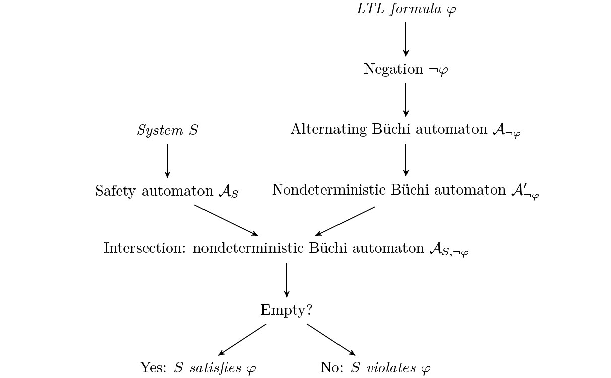
In order to find system executions that violate a given LTL formula (1), we negate the formula (2) and build an automaton that is equivent to the negated formula. For this, we can use the translaton from LTL to alternating automata (3) from Construction 7.1 followed by the Miyano-Hayashi translation from alternating Büchi automata to nondeterministic Büchi automata (4) from Construction 7.2.
Left hand side: Safety Automaton
We represent the system (1) executions as a Safety Automaton (2), which is then intersected (using Construction 3.2 with the Büchi automaton for the negated LTL formula. The actual search for a violating execution then happens as the emptiness check of the resulting Büchi automaton. In the remainder of this section, we first quickly discuss the representation of the system as a Safety Automaton, using sequential circuits as an example, and then focus on the emptiness check of Büchi automata.
Model Checking Sequential Circuits
As an illustration of how automata can be used to represent system behaviors, we consider the representation of sequential circuits to safety automata. For a more general discussion of how to represent different types of systems, such as protocols or software, we refer the reader to textbooks on model checking, such as Principles of Model Checking by Baier and Katoen.
Sequential Circuits
$\textbf{Definition 9.1. } \text{A }\textit{sequential circuit }\text{is given as a tuple }S=(I,O,R,\theta,\lambda,\delta)\text{, where}$
$\begin{array}{lcl}
\hspace{1cm}\cdot&I&\text{is a set of input bits}\newline
\hspace{1cm}\cdot&O&\text{is a set of output bits}\newline
\hspace{1cm}\cdot&R&\text{is a set of registers}\newline
\hspace{1cm}\cdot&\theta\subseteq R&\text{is an initial register evaluation}\newline
\hspace{1cm}\cdot&\lambda:O\rightarrow(2^{I\cup R}\rightarrow\mathbb{B})&\text{assigns to each output bit a control function }2^{I\cup R}\rightarrow\mathbb{B}\newline
\hspace{1cm}\cdot&\delta:R\rightarrow(2^{I\cup R}\rightarrow\mathbb{B})&\text{assigns to each output bit a update function }2^{I\cup R}\rightarrow\mathbb{B}\newline
\end{array}$
Safety Automaton
A safety automaton is a Büchi automaton where all states are accepting. Here, Input $(I)$ and Output $(O)$ are represented as words, and register valuation $(R)$ is represented as states:
$\text{A sequential circuit can be represented as a safety automaton}\newline\mathcal{A}_S=(2^{I\cup O},2^R,I,T,\small\text{BÜCHI} \normalsize (Q))\text{, where}$
$\begin{array}{ll}
\cdot\ Q = &2^R\hspace{1cm}\text{consist of all valuations of the registers;}\newline
\cdot\ I =& \lbrace\theta\rbrace\hspace{0.8cm}\text{corresponds to the inital register valuation;}\newline
\cdot\ T=&\lbrace(q,\sigma,q’)\mid\lbrace\forall y\in O:y\in \sigma\text{ iff }\lambda(y)(q\cup(\sigma\cap I))\rbrace\wedge\lbrace\forall r\in R:r\in q’\text{ iff }\delta(r)(q\cup(\sigma\cap I))\rbrace\rbrace\newline
&\hspace{1.5cm}\text{reflect the outputs specified by the control functions, and}\newline
&\hspace{1.5cm}\text{the new register valuation specified by the update function}\end{array}$
We say that a circuit $S$ satisfies an LTL formula $\varphi$ if $\mathcal{L}(\mathcal{A}_S) ⊆ \mathcal{L(\varphi)}$.
Example
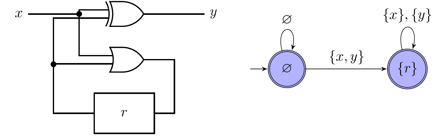
The example circuit shown on the left has input $I = \lbrace x\rbrace$, output $O = \lbrace y\rbrace$, and a single register $R = \lbrace r\rbrace$. The control function of $y$ is $x\text{ XOR }r$, the update function of $r$ is $x\vee r$.
We assume an initial register valuation $\theta = \varnothing$. The circuit is then represented as the automaton shown on the right. Note that that accepting state only have transtions $\lbrace x\rbrace, \lbrace y\rbrace$, becasue if $\lbrace x\rbrace$ holds, $\lbrace y\rbrace$ cannot hold because of the $\text{XOR}$ gate and vice versa.
Suppose now that we wish to verify whether our circuit satisfies the LTL formula $\varphi = \square(x\leftrightarrow y)$. We negate $\varphi$, and translate the resulting formula into the nondeterministic Büchi automaton shown on the left:
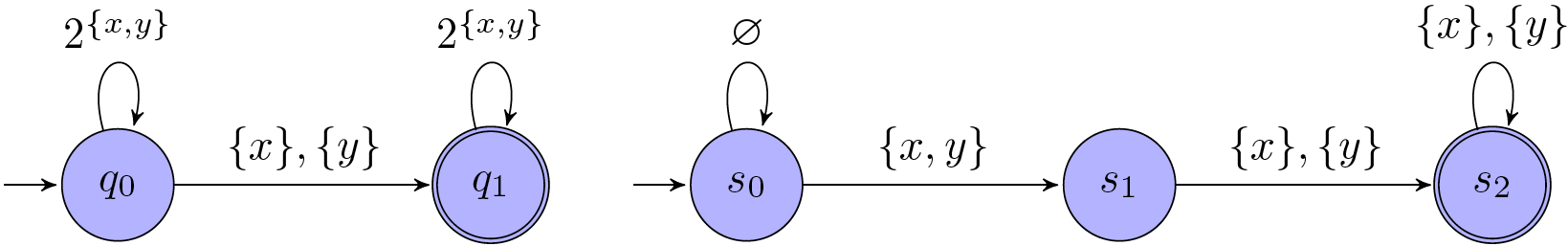
The intersection of the languages of the automaton representing the circuit and the automaton representing the negation of $\varphi$ results in the automaton shown above on the right.
Since there are some words that can be accepted by both automaton and their intersections, the language of this automaton is not empty: for example, the word $\lbrace x, y\rbrace(\lbrace x\rbrace)^\omega$. The circuit, hence, does not satisfy $\varphi$.
Next chapter: Nested depth-first search
Please cite the source for reprints, feel free to verify the sources cited in the article, and point out any errors or lack of clarity of expression. You can comment in the comments section below or email to GreenMeeple@yahoo.com